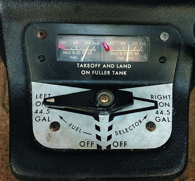
Ignorance is bliss, but there’s a dark feeling when a pilot realizes there is far less fuel on board than the fuel gauges indicate. Get lucky like I once did and you’ll recognize the inaccuracies inherent with aging analog fuel quantity gauges when you’re on the ground.
The next step is chasing the problem, which means removing the instrument for testing and rebuilding and recalibrating the fuel measuring sensors in the tanks. There are some worthy repair attempts, but compare the all-in troubleshooting, overhaul and gauge replacement costs to a new digital system. The system you’re throwing money at may be as old as the aircraft.
Fuel Gauges 101
First, let’s get the regs out of the way. There is the perception that an aircraft fuel gauge only needs to be accurate when the tank is empty and that’s partially true. It’s all about calibration.
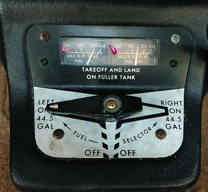
FAR 23.1337 partially says each fuel quantity indicator must be calibrated to read zero during level flight when the quantity of fuel remaining in the tank is equal to a type-specified unusable fuel supply. That could be a sizable amount. Unusable fuel isn’t the same as empty, but it might as we’ll be.
Fuel gauges have been in airplanes since before there were electrical systems. The early cork and wire combination was an accurate and dependable measuring device that required little maintenance. That little bend at the end of the wire bobbing up and down was pretty darn accurate, too. Later, the wire ended up in a glass tube with graduated markings for more precise readings.
Perhaps the next simplest was Jim Bede’s glass tube fuel gauges found on the two-place Yankee/Grumman models. Mounted low on the side of the fuselage, the gauge showed the level of the fuel in the wing tank by using atmospheric pressure and the leveling dynamics of fluids. Pilots flying with these systems were wise to empty the tanks and add measured amounts of fuel to know exactly how much was in the tank at a given level and mark the tube or wire for future reference. But it soon became more complex.
Eventually, gauges had full, half and empty markings—a design that came from the auto industry—bringing some inherent problems. Fuel sloshing at different attitudes, the side effects of dissimilar metals in the tank and a multiplicity of fuel tanks are examples.
Later legacy systems operate on the principle of capacitance. In general, capacitant sensors are pretty bulletproof because they are basically a couple of tubes insulated from one another using the fuel as a dielectric, while electronics handle the resolution.
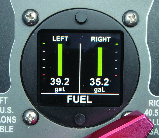
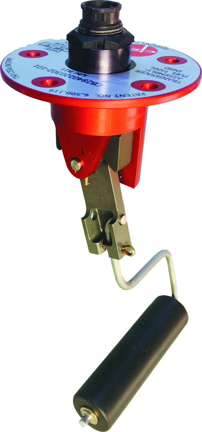
The latest technology is magnetoelectric, which uses—you guessed it—magnets installed in the measuring float. This technology requires the replacement of all existing senders and measures the angle from the fixed sensor to the float, while a precise (and critical) aircraft-specific calibration procedure results in fuel quantity measurements accurate to a tenth of a gallon. See the sidebar on page 19 for more on this digital technology.
Legacy Support
The aircraft maintenance manual is the go-to for working with a particular system. Most of the earlier legacy systems (a tank sensor hooked up to an electrical gauge) used variable resistance to produce a value of measurement, with components scattered about the airframe. Cessna mounted the gauges in the wing roots of very early models, but eventually went to panel-mounted gauges generally built by Stewart-Warner and Rochester, with some AC Delco units thrown in the mix. These companies have long retired from supporting the systems. Luckily, there is still at least some support for ancient systems.
Popular sources for replacement parts are McFarlane Aviation in Vinland Valley, Kansas, and Air Parts of Lock Haven in Pennsylvania. There’s also some repair and exchange support through Keystone Instruments in Pennsylvania and Malkasian Corporation in Arizona.
A typical instrument shop might take in senders and indicators, but many simply send them out for repair or exchange. Before you give the go-ahead to have the system yanked from the aircraft (expect some disassembly and downtime), make sure your shop knows what it is dealing with. It’s possible that the sender or the gauge has once been replaced, which can lead to compatibility issued with replacement parts.
Fuel senders and gauges are a matched set and work within specific ranges of resistance. Common to aviation systems are 0 to 90 ohms for 24-volt electrical systems and 33 to 240 ohms for most 14-volt systems. The aircraft’s service manual should specify which range is correct. Owners who buy gauges and senders at salvage yards or aviation flea markets might not have done their research.
Rose Mumbauer at Air Parts of Lock Haven said a number of units that come in for repair are simply the wrong ones for the aircraft. Moreover, Cessna complicated matters by switching suppliers as often as four times a year with some of its models. Having the aircraft serial number handy is a must when ordering Cessna senders and gauges.
Troubleshooting Technique
Want to tackle the troubleshooting on your own? Testing the old analog components is pretty simple (gaining access might not be) and getting an idea of the fuel sender’s accuracy is accomplished with a common multimeter set at the 2000 ohms measurement. You’ll get the best results if the senders are out of the tank, although it’s possible to get fairly accurate measurements while the senders are installed. Don’t be surprised if you’ll need to empty the tanks during the process, plus problems could be more extensive than faulty senders.
The troubleshooting chase could reveal wiring problems at the back of the gauge, a faulty gauge and of course problems related to the senders. There’s no real magic involved in testing the system. Instead, it’s the disassembly that you’ll pay for. Should you attempt it on your own, it will help to have an assistant to watch the gauge while you manipulate the sender.

Start at the gauge. Once you’ve verified a solid power connection to it, if the gauge reads empty or less all of the time, then there is no resistance and probably a ground short. If the gauge reads full or more (infinite on the tester), then there is likely a broken wire or maybe even corrosion. If the needle moves, but does not correspond to how much fuel you think is in the tank, then there is likely an internal problem or perhaps a calibration problem. The sender is more difficult to diagnose.
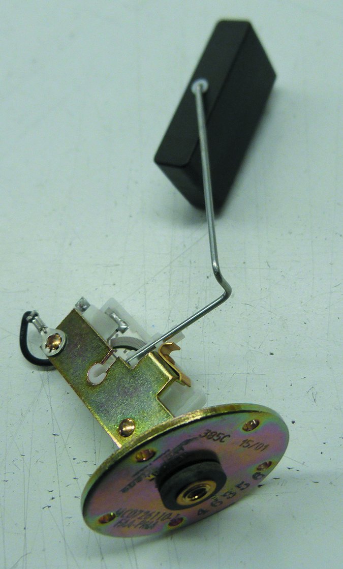
You’ll first have to find it and the access panel that will enable you to work with it. The sender will generally have a round steel plate with an attached grounding lug and a signal lug. For measurements, a wound resistor attached to a long arm is placed in a fixed position, creating a pivot point, and bent as necessary to avoid structural obstacles and to reach the top and bottom fuel levels.
At one end of the arm is a float (either brass or composite), while the other end has a wiper that contacts the resistor. As the wiper contacts one of the wire loops, it reads the resistance to the end of the wound wire. A wound wire creates a specific number of contact/measuring points for the wiper. Some gauges may have nearly 300 reference points for measuring the fuel level. The newer magnetoelectric units have as many as 10,000 measuring points for incredible accuracy.
Keep in mind there is no electricity in the fuel tank—resistance is merely a reading of the length of a specific conductor—which is the wound wire creating the distance from one location to the other.
First, remove the send/gauge lead wire from the center post and touch it to chassis ground. The quantity gauge should read empty and the multimeter should read 0 ohms, as there is no resistance. If it is a 90-ohm system, a full tank would yield 90 ohms of resistance. If you measure 45 ohms, verify that the fuel level is at half. See why doing this with the tanks full is easier? If there is a large discrepancy between the gauge and the meter, you’ve verified a problem with the sender. Read on for your options.
Replacement Senders
The choices are limited when it comes to replacing senders. One option is sourcing them from the aircraft manufacturer. Worth noting is that Cessna sells them through Yingling Aviationin Wichita, Kansas. Plan on roughly $800 per sender. A word of caution: Yingling’s Scott Jantz says the company only sources senders made by Rochester Gauges. This could require gauge replacement for compatibility, which could also mean wiring modifications. The other option is sourcing used senders from a salvage dealers. Wentworth Aircraft and White Industries are two well-regarded sources. I spotted an eBay store that’s run by Discount Aircraft Parts. It sells a variety of used senders and other fuel system components at attractive prices, although slightly higher than others that charge a core fee. While the company says it tests the components, it won’t do any repairs and everything is sold in as-is conditions.
McFarlane Aviation offers new PMA replacements for Stewart-Warner senders for under $400 list, with much lower street prices. Its senders are newer technology with many of the components built to specifications by Stewart-Warner, which no longer supports its legacy units.
From my experience, McFarlane’s replacement senders have an edge over new Stewart-Warner senders and can even be calibrated to replace legacy ones. What goes wrong?
As senders age, they accumulate dissimilar metal corrosion and rust due to condensation, wiper wear and residue buildup on the resistor. The wiper can also deteriorate. McFarlane’s modern transmitters are ceramic plates printed with resistive ink. These have been tested to millions of cycles with no failure of the printed-on resistor element or the wiper. The potentiometer is faced with conductive bars that when contacted by the wiper provide a resistance proportionate with the wiper location, the location of the wiper controlled by the fuel level and float. Unlike wire-wound designs, the ceramic design might last forever.
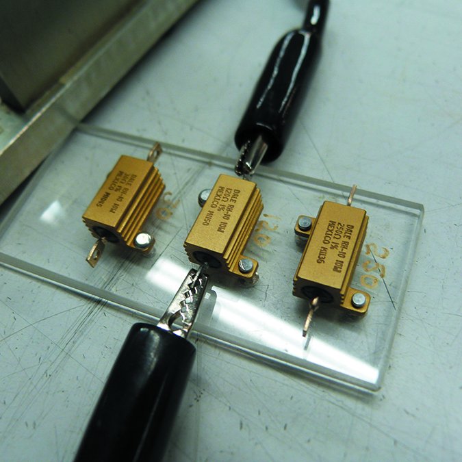
During my research, McFarlane’s Fred McClenahan gave me a tour of the lab and demonstrated how each sender was checked using a consistent reference voltage and with calibrated resistors suitable for the three most common resistance-type fuel indicating systems. The company provides hundreds of PMA replacement Cessna parts at impressive savings to owners and has a sterling reputation.
As for rebuilding existing senders, Air Parts of Lock Haven (established in 1987) is perhaps the most popular. Its sender rebuild prices start at $166.50, plus parts, which makes for a reasonable alternative to the shotgun approach. The company’s gauge overhaul service starts at $144.50 and it can support all three of the legacy brands, including Stewart-Warner, Rochester and AC Delco. Much of Lock Haven’s work involves exchanges, plus it has 12 technicians working on instruments each day. Turnaround is usually less than three weeks. It also has an extensive inventory of senders ready to ship because the company purchases as many cores as it can find. My research revealed that Lock Haven’s selling price for senders is in line with what a repair would cost, plus a core charge.
Malkasian Corporation is a small shop in Arizona that advertises a $400 exchange price and $450 to rebuild your unit if there are none in stock. The shop specializes in Stewart-Warner senders (the old ones) and says the components are relatively easy to repair. It also said that Rochester senders might be repairable at least one time because the resistor film wears out. During the rebuild process, Malkasian uses a newer, denser film to help the units last longer. The company suggests saving older senders because they might be worth repairing. “We are running out of the good ones,” it said.
Operating since 1961, Keystone Instruments in Lock Haven, Pensylvania, works on virtually all aircraft instruments including Stewart-Warner, Rochester and AC Delco fuel senders, plus some lesser common components, including King-Seeley, Lee (used in Cessnas for a short while) and Liquidometer. Keytone’s Gig Bumbarger said wound resistive senders can last forever with the right maintenance. Bumbarger and Fred McClenahan at McFarlane warn that ceramic plate-and-resistive-ink senders made by Stewart-Warner can melt if you accidentally short the poles at the gauge. That’s because when the wiper is at its lower end, there’s less resistance, which can overheat the resistor. Worth stressing is this problem is the result of a short somewhere else in the system or a maintenance accident and not a design or manufacturing problem. This type of thick-film transmitter has been in use in automotive systems for over 20 years and has a pretty good track record. Keep the power turned off when working around the system wiring.
Keystone overhauls (turnaround is a few days) start at $145, plus parts, while exchanges are $195 to $225.
The Future Looks Digital
The future of aircraft fuel gauges seems focused on magnetic senders with digital outputs like the technology found in CIES senders. They’re standard in some OEM applications and the STC list for retrofit is growing.
When it comes to our older aircraft and the ratio of cost to value in modernization, remember that older variable resistance senders were incredibly simple.
I had access to an SAE test report written by a Stewart-Warner engineer that cited test results of the wire-wound resistor. If kept lubricated with fuel (which helps to keep moisture off critical components), the test results proved the senders could last 2,000,000 cycles.
While older senders might be too far gone to salvage, parking the aircraft with the tanks full is a good strategy for preserving good ones.
For mechanical gauges, we like the Mitchell and Sigma Tek options. Like all-in-one digital engine displays, they can be matched to work with existing senders. That might save money.
Digital Fuel Quantity: No Simple Update
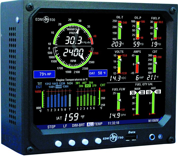
If you’re considering a primary electronic engine display, the integrated fuel quantity function that’s standard on select models—including the JP Instruments EDM930 and Electronics International CGR-30—is a sweet bonus. But don’t expect these devices to be the cure-all for existing fuel measuring problems; the displays connect with the existing fuel senders. It’s a liberal interface, especially with the JP Instruments EDM900 series primary engine display, which is STC-approved for replacing the existing fuel quantity gauge, plus it works with a variety of existing fuel senders.
If a big screen engine display is more than you can budget (it could require sizable instrument panel modification) you could replace the analog gauges with a digital smart gauge like the one made by Aerospace Logic. The FL202 series display fits in a 2-inch instrument cutout and, aside from the senders, is a one-piece system. STC-approved as a primary fuel quantity gauge, the FL202 has a 65,535-color LCD display and connects with the senders through a DB25 interface connector.
Keep in mind the system doesn’t display fuel flow or any engine data. You’ll need a fuel flow computer or engine monitor with fuel computer for that. The FL202’s primary data—which is fuel quantity—is on an uncluttered display that’s intuitive to interpret at a glance. There’s also a fuel imbalance warning, which is set during programming. A flashing yellow bar on either tank designation indicates a fuel imbalance condition, which serves as a reminder to switch fuel tanks. There is also a trend-graph function, which provides a scrolling line graph of the total fuel used from each tank since the last power cycle.
Aerospace Logic’s STC requires the use of the CIES magnetoresistive digital fuel sensors. As mentioned in the main text, magnetoresistive senders have more precision than old-school senders, plus they work we’ll under extreme temperature fluctuations and are compatible with alternative fuels. We retrofitted a CIES system (with the FL202G control head) in a first-gen Cirrus with poor results, but the inaccuracies had more to do with limitations of the fuel tank design. The system is said to be flawless in other models, and CIES senders are used by OEMs, including Cirrus. Expect an installation that approaches or even exceeds $5000. For that money, it’s worth pricing a primary engine data display, while addressing any problems that might exist with the current fuel senders.

