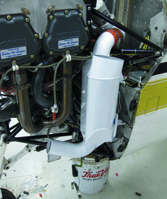
Based on calls and letters we’ve fielded, there’s a certain mystery that surrounds engine intercooling systems. But there’s no mystery because simply put, an intercooler is essentially a radiator, or heat exchanger. That’s the key to engine longevity, of course.
But aftermarket intercooling systems add complexity and can crowd already tight engine bays on turbocharged aircraft. For engines that have efficient turbos, an intercooler might not do much. For others—especially those plagued with high cylinder head and turbine inlet temperatures—the investment could be worth it. Here’s a deep technical analysis to help with the decision, and some tips for assessing a given design.
It’s About Lower Temps
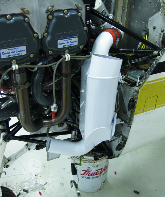
An intercooler’s goal is fairly simple: Reduce induction air temperature. If you had a simple Ideal Gas Law PV=nRT compressor, the simple fact of compressing gas (in this case, ambient air) from, say, 10 PSIA and 23 F (at roughly 10,000 feet) back to sea level pressure of 14.7 PSIG would heat the gas. But, in addition to that ideal gas behavior, our turbocharger compressors have other inefficiencies, like internal recirculation and heat transfer from the cowling environment, that heat the gas further. It’s not uncommon to see compressor discharge temperatures (CDT) over 200 degrees F at middle altitudes and over 300 F in the flight levels.
Now, having compressed air is a good thing; it allows the packing of more fuel/air mixture into the cylinder on each combustion event cycle, thereby allowing delivery of more horsepower to the propeller. However, there are downsides.
The associated elevated air temperature can cause wear or deterioration of induction system components (turbocharged through-the-carburetor engines commonly have a 240-degree redline on CDT to avoid cooking the carburetor’s seals).
But more importantly, elevated induction temperature increases the detonation tendency of the fuel. Cessna’s Cesar Gonzalez estimates (in various ASTM papers) that increasing induction air temperature (IAT) by 10 degrees increases the fuel octane requirement by one octane number. Or, in FAA speak, increasing IAT decreases the regulatory required detonation margin offered by the certification-required 10 percent higher-than-demonstrated-no-problem fuel flow.
Efficiency and Detonation
Let’s step back and look at the goal of an internal combustion (IC) engine. Converting chemical energy into mechanical energy is a fairly inefficient process, but IC engines are better than the steam engines of yore. And the higher the compression ratio of the engine, the more efficient the energy conversion. So why don’t gasoline piston engines have 20:1 compression ratios like diesel engines do? Because of destructive detonation.
As you compress and heat the gasoline/air mixture, the temperature rises, and increased temperature increases the rate of almost all chemical reactions. Detonation occurs when the air/fuel mixture is ignited and the flame front begins burning across the mixture in the cylinder, increasing its pressure. As that flame progresses, the “end gas” (the portion of the air/fuel mixture that hasn’t combusted yet) gets compressed and heated more and more by both the combustion pressure wave and by the infrared heat radiation from the ongoing combustion, moving at the speed of light into the end gas.
For every fuel and fuel/air ratio, there’s a critical temperature/pressure at which combustion ceases and detonation begins: combustion moving faster than the speed of sound, creating a sonic boom shock wave. Making the incoming air hotter moves the entire process closer to that critical temperature/pressure point.
Detonation can have a couple of negative effects. Light to moderate detonation is actually fairly we’ll tolerated by most aircraft engines and isn’t that uncommon. The DC-7 and Lockheed Constellation routinely completed long overwater flights with all four engines operating in light detonation. But there’s a limit.
Severe or extreme detonation can quickly lead to engine destruction directly, or by launching preignition, which can destroy an engine in seconds. The destructive mechanisms are temperature and pressure: As the combustion moves from moderate to severe detonation, the pressure pulses inside the cylinder disrupt the boundary of stagnant gas along the internal surfaces of the cylinder head. This greatly increases heat transfer from the ongoing combustion to the cylinder head.
At the same time, the detonation causes these temperatures to rise. During significant detonation, CHTs that begin in the 300-degree range may increase by one degree F every couple of seconds, something that has been observed and documented. If not arrested by engine control inputs, the cylinder head temperature will rise so high that the aluminum alloy of the piston will deteriorate. This can directly lead to gas leakage at the edge of the piston.
In addition, over time the high peak pressure pulses associated with the moderate to severe detonation can cause the top ring to crack. That, too, causes large leaks of hot exhaust gas down the side of the piston. While the cylinder heads or assemblies rarely fail, the pistons and rings do fail as a result of detonation. If the detonation persists long enough, with say, high moderate to low severe detonation, objects in the cylinder environment get heated hotter and hotter and some items—maybe a part of a spark plug ceramic (which can crack due to the detonation) or the tang of a helicoil— will start to glow red hot. Once the glowing part gets hot enough, preignition begins, and the CHT can rise several degrees per second (as opposed to several seconds per degree with detonation). This gets the cylinder to “come from together” time very quickly, maybe more quickly than some pilots can notice, analyze and react to. So, these overheating and destruction processes are good to avoid; at the same time getting more boost to the engine is a good thing. So, since detonation tendency is correlated with IAT, let’s simply lower the IAT through intercooling, right? It’s not that simple.
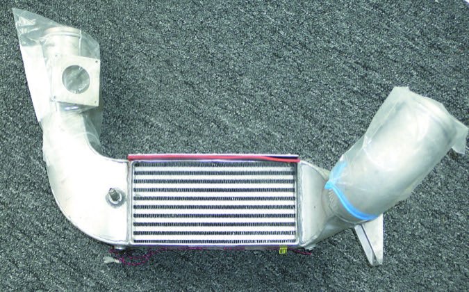
The intercooler imposes a flow restriction on the induction system, causing a pressure drop across the flow resistance of the intercooler. That’s OK; the turbocharger typically has a control system on it, so to achieve the design point induction pressure, the wastegate will close a little, and the turbo will work a little harder to overcome the insertion pressure drop of the intercooler. So now we’re back to the same induction air pressure as before, but at a new, cooler temperature. The cooler air is denser, so at the same induction air *pressure* more oxygen is available, so more fuel can be added, and more power delivered. Sounds great, right? But, the FAA and others get concerned.
That’s because now you’re asking the engine to deliver more power than it was certified for, so although you’ve increased the detonation margin by cooling the induction air, these naysayers want you to also reduce the induction air pressure to keep total oxygen available constant, before and after intercooler installation, and hence keep power constant.
Unfortunately for pilots using these systems, and to the discredit of the system manufacturers and certifiers, that’s not how the real world works. If you actually put a turbocharged engine on a test stand and then observe the effect of the intercooler, you’d find that, say, 32 inches of MP and 200 degrees of induction air input deliver almost the identical horsepower as 32 inches of MP and 120 degrees of induction air.
So unlike obeying the restriction of the STC and reducing manifold pressure so many inches per 10 degrees of cooling, leaving the manifold setting alone delivers the same power, with safer-for-the-engine conditions. How?
Remember when I explained how the intercooler imposes an insertion loss on induction air pressure, but no worries, the turbo control system will compensate? There are no free lunches. It turns out that the additional back pressure on the engine exhaust from the wastegate closing just a little bit to maintain induction pressure through the intercooler reduces engine power output just enough to offset the increase that would otherwise occur from the denser charge. It may not be obvious why such a conservation-of-engine-output effect would occur, but for efficient intercoolers, that’s the relationship.
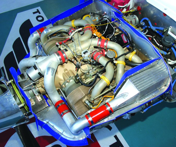
Of course, some installations are markedly inefficient, and insertion of the intercooler imposes excessive induction pressure losses, and the turbo compensation for that actually reduces total power output. But, reducing allowable manifold pressure makes that even worse, which isn’t a solution. In my view, it just suggests that mod developers need to be even more circumspect and analytical than they have been historically.
Installation Factors
Now that you’ve got a deeper understanding of how intercooling works, maybe you want an intercooler to allow you to maintain relatively high engine output even on hot days when, otherwise, IAT limits might cause you to run further away from peak (either richer or leaner) to protect the engine and reduce power output.
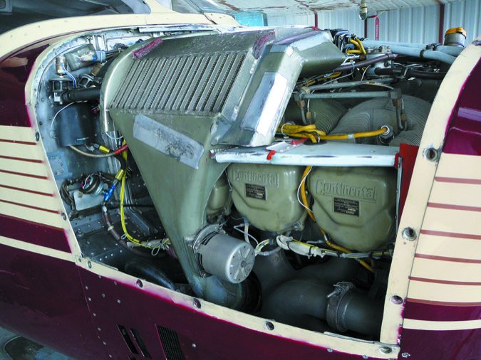
First consider the location for the intercooler. It needs an uncomplicated-as-possible path between the turbo discharge and the induction system intake. And it needs ready access to cooling airflow that doesn’t overly complicate overall engine cooling. And it would be best if there’s nothing nearby, like exhaust risers or cabin heat dump valves, that will actually HEAT the intercooler, turning it at least partially into an interheater instead of intercooler. Finally, the location needs to offer a decent mount system to resist cracking of both the intercooler and the attachment points from engine vibration. Second, it’s critical to synthesize the induction air path. On some aircraft that’s easy; on others, Rube Goldberg would be challenged. Third is that good cooling airflow is a must, but without compromising engine cooling.
On that design note, over the years most intercoolers have been derived from General Motor’s Harrison Division designs. And conveniently for aircraft designers and modifiers, GM Harrison provides a design guidebook. But, it’s a potential trap. Cooling airflow for trucks (the primary Harrison intercooler market) and automobiles is very different than cooling airflow for aircraft. Due to the much higher speed of aircraft, higher “upper plenum” pressures are available. But, due to cooling drag concerns, volumes of cooling air are limited, at least if one wants to avoid slowing down the airplane. As such, as tempting as it is to use the correlations and design notes offered in the Harrison guidebook, and that is still a good place to start, one must think carefully about what’s different in an aircraft installation, and what our overall goals are in cooling system design. One can argue that this hasn’t often been done well. Last, the system has to be maintenance-friendly.
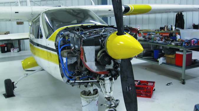
Achieving simple design beauty isn’t always possible; my own plane, a turbo Cardinal RG boasting the Cardinal Cruiser III configuration by Tornado Alley, posed a significant design challenge. There was a great place for the intercooler on the pilot’s side firewall, far from the exhaust system. The cabin heat dump valve could be deflected. Cooling air is readily available from the top of the engine and the exit path is short and clear via the cowl flaps. But, the induction plumbing!
The original Cardinal Cruiser I design had only a 3-inch hose between the turbo discharge and the fuel injection servo air inlet. But, to get the intercooler in on the act requires over six feet of induction plumbing. It’s a credit to Tornado Alley’s engineering department that the entrail is so nicely designed, routed and supported, while avoiding significant pressure drop. It requires changing from the larger Bendix mags to the smaller (and in the process, pressurized) Slick mags to make room for the plumbing and my mechanic impugns my Hungarian ancestors every time he has to adjust the governor’s prop control rigging. But overall, it’s fairly elegant, for being a snake in a briefcase.
This paying attention to details is the core of turbo system design. Recall that in the early days Cirrus decided to design its own turbo system. At the time (around 2007), Dale Klapmeir told Aviation Consumer that after flying the system in-house it determined the system was a good performer (although not without cooling issues) and surely recognized the benefits of turbocharging, but it dropped it because of the uncertainty in 100-octane fuel. It dropped the project and bought the entire pre-engineered turbo system from Tornado Alley Turbo, which launched the turbonormalizing of the SR22 on its own. TAT had demonstrated good aftermarket capability, and a new clean-sheet design developed entirely by Tornado Alley Turbo convinced Cirrus to jump back into that market. It sold about 500 new turbonormalized Cirrus aircraft in the first 12 months.
TAT came up with a more elegant induction air routing scheme to minimize pressure loss, ambient heating and other ills. Plus, it carefully designed the intercoolers themselves to exactly match the under-cowling cooling air pressure/flow characteristic, which not surprisingly couldn’t be just lifted from GM’s diesel truck intercooler design rule-of-thumb book. The designer even came up with an intriguing cabin heat design. Cabin heat is normally a bugaboo of turbo retrofits as the traditional muffler heat exchange goes away due to lack of space and lack of necessity (turbos are great mufflers, with spinning parts inside), but turbo airplanes really do need heat. The Cirrus system included a cabin heat exchanger with a unique safety feature: If the system cracks, exhaust gas will not leak into the cabin because the cabin air is at higher pressure than the exhaust gas at the cabin heater. Instead, cabin air will leak into the exhaust. That engineer deserves the Carbon Monoxide Poisoning Jonas Salk Award and I’d plan the award banquet.
Wrap It Up
Intercooler mods need to have STC approval, of course, so you’ll need to find one for your particular aircraft. We scanned the market in the September 2015 issue of Aviation Consumer and a follow-up reveals there are a few choices. In addition to Tornado Alley Turbowww.taturbo.com,. there’s American Aviationwww.americanaviationinc.com. with its replacement Ultracooling system for Cessna 340 and 414 twins. Installation could take around 45 hours and the kit is north of $15,000. There’s also a kit for Piper Navajo models. Turbopluswww.turboplus.com. has a wide range of intercooler and induction systems for Piper, Beechcraft, Cessna and Mooney models. It says installation ranges from 20 to 30 hours, while prices start at around $5000.
As mentioned, maintenance is an important consideration so talk with your shop for feedback on what it might take to maintain one on your particular engine.
Contributor Paul Milner is the technical editor for the Cardinal Flyers Online type club and owns a turbonormalized C177 RG based in California.

