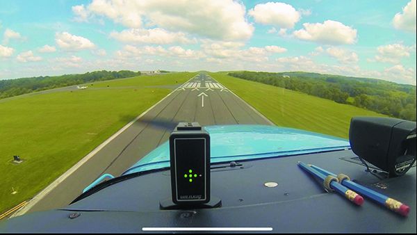
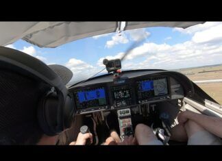
You’ve heard the arguments—more stabilized and consistent approaches and landings, more confidence while maneuvering, better aircraft control and less wear and tear on the airframe and the tires. Yes, an angle of attack system offers all these benefits.
Are there any drawbacks? We haven’t found any. So, if you haven’t installed one, perhaps we can entice you with a fresh survey of the market.
BACKGROUND, DESIGNS
Aircraft stall at only one angle of attack, the critical angle of attack. You can reach the critical angle of attack in any attitude, in any configuration, at any weight and center of gravity, at any maneuvering load factor, and all of these factors determine the airspeed at that instant that corresponds to the stall. So using the airspeed indicator—which shows the speed at stall under very specific conditions—to manage your lift is, well, not particularly meaningful outside of those specific conditions.
Devices to measure the angle of attack (AoA) have been around for a long time, but since we continue hitting the ground from an inadvertent stall or stall/spin—often in the pattern—the FAA took steps a few years back to simplify the certification procedure for AoA devices so they can be installed as a minor alteration. The FAA hopes that getting more AoA sensors out there will decrease the number of accidents.
Angle of attack measurement solutions range from basic mechanical devices to complex systems that calculate AoA. You could, for example, rig up a contraption on the wing with a vane that aligns itself with the relative wind—like a weather vane. The visual difference between that vane and the wing is essentially angle of attack.
There are commercial systems that mount such a vane on a mast. The system detects the angle of the vane and displays the angle in the cockpit. Sophisticated (and expensive) versions of this system have been used on high-end and transport-category aircraft for quite some time, and typically mount a vane on the side of the nose.
Physical sensors, of course, are susceptible to ice and some have heated versions. Otherwise, they have the potential for the highest accuracy and consistency. Note that any accumulation of ice on the airfoil changes its shape and potentially the stagnation point (explained below) and critical angle of attack. Some AoA manufacturers make this point, saying there’s no need for ice protection on their probes because the readings in ice could be erroneous. We believe this is a specious argument—at the very least, some information is better than none, particularly in ice.
It’s possible to use a short mast or probe with a couple of ports calibrated such that the air-pressure difference between those ports corresponds to angle of attack. There are no moving parts. In normal flight, these differential-pressure systems approach the accuracy of a physical probe. However, in asymmetric flight (slips, yaw, etc.) the pressure differentials can be inconsistent and lead to errors. Further, flying in precipitation has been known to cause jumpy irregular readings that the pilot must mentally average out.
With the recent availability of inexpensive accelerometers and solid-state gyros, it’s possible to calculate AoA. Similar devices form the AHRS (attitude and heading reference system) used in EFIS so there are no actual spinning gyros. These devices can be used to tell the AoA system the pitch of the aircraft and the path of the aircraft through the air, from which the AoA can be determined.
But, there’s a potential for errors from the atmosphere. Say you’ve encountered a significant downdraft or worse, a microburst. The air mass in which your aircraft is located is moving down, even as you’re flying through it normally. Thus, you might have a minimal angle of attack, but with the overall path of the aircraft being downward from the downdraft, these calculated AoA systems can falsely read a high angle of attack.
The pilot responds to that false-high AoA probably by adding power (a good thing) but also possibly by lowering the nose (a bad thing if close to the ground). In these scenarios, the pilot should be aware of the potential for false-high AoA readings and plan for the correct response.
At least one manufacturer of a calculated AoA system makes the claim that this falsely high AoA should be viewed as a sink-rate alarm, making this an advantage over the other types. You should decide if you’ll react correctly to a high-AoA alarm if you’re on approach, in the soup, with thunderstorms and possible microbursts in the area.
STAGNATION POINT
Visualize an airfoil in normal flight. Air approaches the leading edge of the airfoil and the airflow separates. Some of the air will flow over the top of the airfoil and some will flow under. The point at the front of the airfoil above which the air goes over the top and below which the air flows under the airfoil is the stagnation point.
As the airfoil’s angle of attack increases, the stagnation point moves down/aft on the airfoil. This is the principle on which most OEM stall-warning systems are built. In normal flight, that little tab is pushed down by air flowing under the airfoil. But nearing the stall the stagnation point moves behind the tab and air trying to flow over the top pushes the tab up.
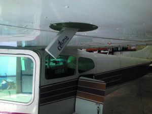
Safe Flight Corporation manufactures many of these OEM stall-warning tabs. They took that knowledge and modified the tab. Instead of merely sensing the up or down position with a switch, Safe Flight’s SCc system actually measures the position of that tab to determine the stagnation point and thus the AoA.
Any lift-altering device changes the chord of the airfoil. Since AoA-measuring systems are concerned primarily with non-transient changes to the main wing, we can confine our discussion to flaps. A complete AoA-measuring system will compensate for chord-angle changes from flaps. While most of what’s available to GA has no such compensation, the manufacturers reasonably make the point that it’s not flaps-up flight that is of most concern. The trouble area is in the pattern, where you’re slowing and adding flaps. They simply recommend that you calibrate the system with full flaps, in the landing configuration.
With all that discussion behind us, let’s now take a look at what’s available. We’ve confined our market survey to systems approved for installation on certified aircraft. Note that there are a number of other systems of all types that are restricted to experimental aircraft. We’ve not included these.
PHYSICAL SENSOR SYSTEMS
General Technics offers the $625 CYA-100 system (CYA ostensibly for “check your angle”). It consists of a fixed mast to be mounted under the wing. On one side of that mast, toward the bottom, is a pivot. Attached to the pivot is a bar. The rear of the bar holds a flat vane that’s parallel to the wing. That mounting bar extends far enough forward to act as a counterbalance. Thus, the vane pivots to remain in the airflow and its angle is read and transmitted to the display processor module, which is mounted on the instrument panel. That module contains both the needed electronics and 10 color LEDs that depict the measured AoA.
The system operates on 7-35 volts DC, making it a player in a variety of aircraft, although the probe is not heated. Merely three wires connect the probe to the display processor, so finding unused pins in wing-root electrical connectors is quite possible, facilitating installation on a pressurized aircraft.
The display, which is intended to be mounted in the instrument panel, is simply 10 LEDs—three green at one end, three red at the other, and four yellow in the middle. There is no “donut” to depict target approach speed. Unlike all the other systems here, the display is to be mounted with the red LEDs that indicate high AoA (near stall) at the bottom, and the green LEDs at the top. To us, this seems counterintuitive and since the display is otherwise symmetrical, we might find ourselves “accidentally” mounting it upside down so the red is at the top. The CYA-100 is available from Aircraft Spruce for $625.
As noted, the Safe Flight SCc is an AoA measuring system that relies on a leading edge wing tab that you’d probably mistake for your OEM stall sensor. The tab, however, isn’t just an up/down switch; the system actually measures the position of the tab to detect where the stagnation point is to determine the current angle of attack. It’s a clever system and the only one like it.
The transducer or sensor assembly actually mounts that tab in a cuff that is intended to be mounted on the leading edge of your wing. Approvals require an existing Safe Flight stall-warning system, and the SCc’s transducer is mounted in the same place as the existing stall-warning sensor, but on the opposite wing. The transducer is not heated and the cuff precludes mounting the SCc on a wing with de-ice boots. Further, Safe Flight says that the cuff should not be painted. This makes the installed system rather restrictive and obtrusive.
The system operates on 14-28 volts DC and consists of the transducer and the “indexer,” Safe Flight’s name for the display with integrated system electronics. Interconnecting the two is an eight-conductor cable with RJ45 connectors on the end. (Think Ethernet cables.) This, then, would be challenging to install on a pressurized aircraft without creating a new pressure vessel penetration requiring a DER signoff (unless you happen to have eight spare pins in an existing connector).
Like the CYA-100, the display is merely round LEDs in a vertical stack. But, the SCc display does mimic the donut with some outboard LEDs at the location of the approach AoA. The display also offers a user-settable bug. The SCc comes with a ball mount that is intended to put the display on the glareshield.
Since you’ll be installing this on an aircraft with an existing Safe Flight stall-warning system, we’d love to see a different version of the SCc that replaces the OEM stall-warning tab with the full transducer assembly (available heated) that would presumably have outputs to drive the existing stall-warning system. This would allow the system to be installed on an aircraft with de-ice boots and would keep the transducer clear in ice. The SCc is priced at $2290 direct from the manufacturer, with some discounts available.
DIFFERENTIAL-PRESSURE SYSTEMS
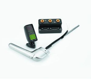
Alpha Systems AoA has the most offerings of all the products we saw. Alpha offers multiple different displays—chevrons with a center donut, bar display, glareshield or panel mount, and even a HUD. Other options include a second display, a heated probe and even a flap sensor allowing different calibrations for up to four flap settings. They also offer a version that feeds the pressure tubes from the probe to remote electronics intended to be mounted in the wing. That communicates with the main processor by four wires, facilitating installation in a pressurized aircraft so long as there are four unused pins in an existing connector.
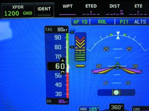
The standard, one-display, non-pressurized version consists of a probe, processor (“interface module”), the display and a separate switch panel with some user controls, but is primarily used for setup and calibration. The system operates on 12 or 28 volts DC.
The probe is a fixed mast and tubing connects ports in the mast to the electronics. Probe location is reasonably flexible with the obvious restrictions of keeping it away from anything that will disrupt the air pressure it sees. In multi-engine aircraft, the probe can even be mounted on the nose. Anybody’s heated probe requires current likely in excess of existing wiring capacity, so it could require additional wiring.
Although we prefer a physical sensor, Alpha Systems offers the broadest range of installation options and system configurations. Because of this, their products deserve serious consideration. Now, if they only made a physical sensor probe.
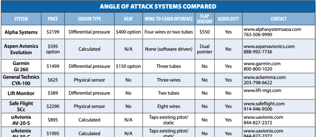
The basic kit is $2199 from the manufacturer or many other sources. Some discounts are available. The pressurized version, heated probe, and the flap sensor are $2899, $400, and $550 respectively.
Bendix King has offered the KLR 10, but that system appears to have been discontinued, although some might still be in the distribution channels.
Garmin’s differential pressure AoA system is the GI 260, and confusingly the GI 260 nomenclature refers both to the indicator alone and to an entire system. And that system includes the GAP 26 probe (available in unheated and heated form in both 14- and 28-volt versions), the GSU 25(C) processor and the display unit. Garmin’s G3X Touch integrated avionics system includes an onscreen AoA display, eliminating the need for the GI 260 AoA display.
Garmin’s probe isn’t a mast like the others. Instead, it looks more like a pitot tube, but it does mount under the wing in the typical location. From the probe, three (not two) tubes are run through the wing into the cabin and attach to the processor/air data computer. This, then, is wired to the display.
The separate GI 260 display, like most of the others, mounts on top of the glareshield. At the bottom are wide, horizontal green lines for low angle of attack. The highest of those green lines has a dot in the middle to represent the “donut” we’ve talked about that is the sweet spot on approach.
Above those are two horizontal yellow lines and two V-shaped yellow chevrons pointing down, the lower of which intrudes on the top horizontal yellow line. Above that are two red chevrons that indicate high AoA, nearing stall.
The complete system with an unheated probe is $1499 and $1649 with a heated probe. It is available through—and must be installed by—a Garmin dealer.
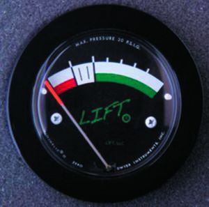
The Lift Monitor system is both the simplest and least expensive system we found. At $389 direct or from a reseller, the system consists of a plastic mast (no heat) that you mount under the wing like most of the other systems. Tubing is run from the probe’s two ports directly to a round gauge placed either in the instrument panel or in a bracket on top of the glareshield. That’s it—no power, no wires, just those two tubes.
The indicator is a round gauge, with a needle that moves with the pressure changes. It’s simple and intuitive to read, with high AoA on the left and low on the right with the proper pitch changes. This is in contrast to all the other systems with a vertical display.
Calibration of most of these devices involves telling the processor when you’re at the various phases of flight. Calibration of the Lift Monitor involves simply changing the angle of the probe’s mounting under the wing. While simple, this might we’ll require multiple calibration flights.
CALCULATING SYSTEMS
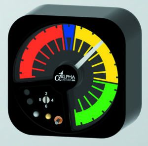
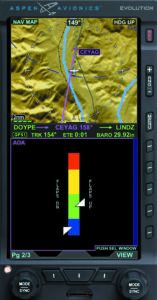
Aspen Avionics offers an AoA display as a $595 option on their Evolution Pro and Evolution Max PFDs and MFDs. The AoA indication is a color-coded band from blue (bottom, low AoA) through green, yellow, and red (top, high AoA). There are two pointers; the lower one reads AoA with flaps down, and the upper reads AoA with flaps up, which strikes us as a clever and simple way to implement flap compensation.
Installation amounts to a software update applied to the unit by a dealer to incorporate the AoA function, followed by a calibration flight. All functionality is contained within the display, so no new connections are required.
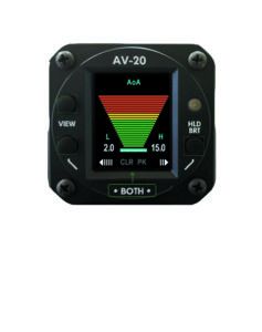
The uAvionix AV-20-S flight display has an integral AoA, in addition to attitude, true airspeed, G-meter and a variety of other functions that we’ve reported on in the May 2020 Aviation Consumer in the budget IFR upgrade report. We think it’s a useful and highly configurable instrument whose capabilities belie its $895 purchase price, and the AoA feature sweetens the deal.
Required connections are limited to aircraft pitot and static lines and 10–32 volts DC power. Optional connections support an external temperature probe, output to a compatible audio panel for aural warnings and remote control of a uAvionix tail/sky/xBeacon ADS-B device.
The AoA display in the AV-20-S can be full screen, or on a screen with other information. The full-screen AoA is displayed as a series of horizontal lines from green at the bottom (low AoA) through yellow and then red on top (high AoA, approaching stall). The lines are arranged in a wedge shape with the red lines at the top being longer and the green lines narrower at the bottom. There is no “donut.” When AoA is displayed as simply a small field on other pages, the display is similar but the lines are of uniform length.
At press time in mid-October, the approval of the AV-20-S excludes pressurized aircraft. Although since there are no required connections that would penetrate the pressure vessel, uAvionix said it is investigating getting that restriction removed.
For a larger presentation, the AV-30-C fits in a 3 1/8-inch standard instrument cutout and now has AML-STC approval for a variety of low- to medium-performance singles. Multi-engine models are excluded.
The AV-30-C sports an extraordinarily large range of functions. It can serve as a primary attitude indicator or as a primary heading indicator, replacing those existing instruments in your panel (thus the STC AML). Both displays are versatile, but the AI in particular can utilize almost all of the “dead” space—of which there is a surprising amount—to also display a myriad of other data, such as airspeed (with color bands), altitude, AoA, G-Meter, etc. The display can be very dense, so it will likely take some familiarization to read things at a glance.
The AoA display consists of stacked colored horizontal lines, similar to that in the AV-20-S. These lines don’t get longer, but do get fatter as the derived AoA increases.
Connections on the $1995 AV-30-C are the same as the AV-20-S, but add an input for standard GPS serial data.
PICKING ONE
Since we didn’t have an opportunity to fly with each of these systems, our conclusions are based solely on our impressions from extensive research on the physical and electrical installations and the feature sets. While it’s our job to recommend what we think is the best one, that’s not really possible with AoA systems because of the wide differences in application and installation approval. But there are some obvious choices.
No electrical system? The simple Lift Monitor system is worth considering because it doesn’t require electrons to function.
If you’re thinking of installing a new electronic attitude indicator and an AoA, you might consider the AV-30-C if your aircraft is on the AML. It’s likely the least expensive on your list of candidate AIs, and it includes an AoA as standard. If total cost is a concern, the AV-20-S should be considered. It’s inexpensive and the installation costs are among the lowest here, with only power connections, and it taps into the existing pitot and static lines—that are likely nearby on the instrument panel anyway.
If you might fly in ice and want the AoA system to keep working, only the Alpha or Garmin differential-pressure systems offer heated probes. You could also choose one of the calculating systems. Got an Aspen? We think adding the AoA option is a no-brainer.
Pressurized aircraft could face some challenges if there’s a need to penetrate the pressure vessel; some of the installation instructions require that existing connectors or holes must be used. But some just don’t address pressurized aircraft. Regardless, if you choose to install one of these and need a new penetration through the pressure vessel, we’d consider (wink, wink, nod, nod) making that a two-step process.
First, get a DER to approve new holes or connectors for future use, create them, and make that log entry. Then in a separate log entry use those “existing” holes or connectors to install your chosen AoA system.
With those specific-condition recommendations out of the way, we do have general recommendations. As long as an unheated probe is OK, we like the CYA-100 for its low cost and use of a vane to directly determine the AoA.
Although we like the engineering elegance of the Safe Flight SCc and its solid performance when we flew with it in both a Cessna Skyhawk and a Beech Baron, the installation requirements make it more complicated than any of the others.
Of course, if you want to go all in with a heated probe and even flap-position sensor, the Alpha Systems AoA products are a good choice, especially if you have a pressurized aircraft. However, if the flap sensor isn’t important to you, Garmin’s system is also good choice at a lower price.
With installed prices ranging from under $1000 to over $4000, you have many options to explore this safety-enhancing instrument. Pick one.
Contributor Frank Bowlin is the Editor of sister publication IFR magazine and wants AoA in his pressurized, known-ice-equipped piston twin. To keep matters simple, he’s waiting for uAvionix to get the non-pressurized restriction lifted from the AV-20-S mini EFIS.

